
Flex System
Anchor Plates
|
|
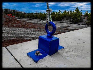
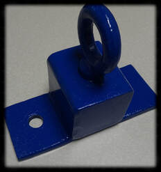
The first component we will discuss is the anchor plate. Fabricated using A500GradeB steel, with a 3/4 eyebolt connection point.
The anchor plate is installed using two 1/2 x 8in concrete screw anchors. The anchor plate can be installed either vertical or horizontally, however, installing plate in vertical position is suggested. Being that every job is different, it is up to the user to decide which position is best for you. For help with installation, please refer to our system setup advice webpage.
The anchor plate is installed using two 1/2 x 8in concrete screw anchors. The anchor plate can be installed either vertical or horizontally, however, installing plate in vertical position is suggested. Being that every job is different, it is up to the user to decide which position is best for you. For help with installation, please refer to our system setup advice webpage.
Vertical Cables
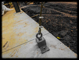
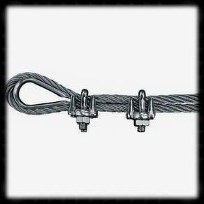
Starting from the anchor plate, we move up to the vertical cable. This cable connects the anchor plate to the system base, we will discuss the system base more in depth later. The vertical cable absorbs most of the fall forces, transferring energy from the horizontal cable, to the anchor plates and concrete. For that reason, this cable MUST BE at minimum 3/8 diameter, preferably galvanized. Just like all of our other cable connection points, cable must be installed using at least two cable clamps and a thimble. For more info, refer to system setup page.
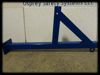
System Base
|
|
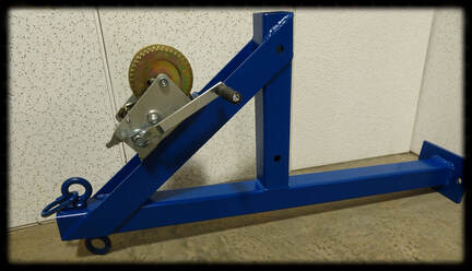
Our next component is the system base or bases. Fabricated using A500GradeB steel. We have two bases; one with a crank, and one without. Both are designed the same, one just has a crank and a couple other safety components. Base with crank, always pairs with base without crank. Each base is attached to a rafter or "I" beam using two 3/4in bolts. Bases must be attached at purlin clip, generally approx. 15ft apart(varies depending on lanyard length, job, restrictions, etc).
As mentioned previously, the vertical cable attaches to system base via 3/4 eyebolt on bottom of base, then down to anchor plate.
For more information on install, refer to our system setup webpage.
As mentioned previously, the vertical cable attaches to system base via 3/4 eyebolt on bottom of base, then down to anchor plate.
For more information on install, refer to our system setup webpage.
Top Pole (Mast)
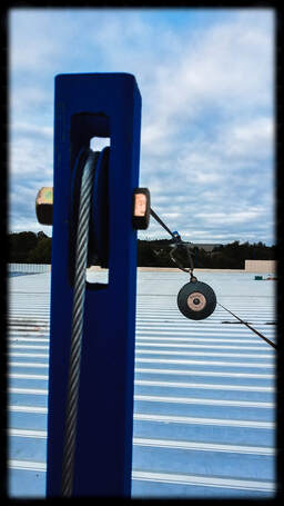
Moving on to the top pole, or mast, whichever you prefer. This component is key to our systems energy absorbing properties, as demonstrated in our many test videos. Made from the same high quality steel as the system base. There are two different top poles, one for each base. The pole with the cable sheave(in both pics) always connects into the base with crank and safety chain. Once masts are inserted, you simply secure the pole to the base with two 5/8in bolts or pins. The masts can be somewhat awkward to handle at times, but using a lift to get above the base helps make it much easier to insert the pole into the base. Always remember to wear fall protection when using lifts and while installing the safety system. Also be sure to clear any personnel from below you while installing the system.
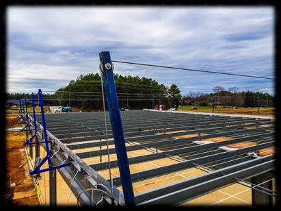
Horizontal Lifeline (cable)
|
|
The final component of the fall protection system we will mention, is the horizontal lifeline. We use a high quality 5/16in galvanized steel cable. And like every cable connection on the system, you must use at least two drop forged clamps and a thimble. Always make sure your cables are in good shape prior to use. Check for kinks, frays, or signs of excessive wear. If any defects are found, remove from service immediately and replace. For installation help, please refer to our system setup page. If you can't find your answer on there, please give us a call. we will be happy to answer any questions you may have.
THANK YOU FOR ALL YOUR SUPPORT, IT IS VERY APPRECIATED!!

|
|